HDLBits答案(24)_由波形图描述电路
由波形图描述电路
前言
欢迎来到HDLBits系列的第24篇!今天的主题非常有意思——由波形图描述电路。顾名思义,就是给我们一个波形图,让我们根据波形图来写出对应的Verilog代码。
为什么我们需要学习这个技能呢?因为在实际的工程开发中,我们经常会遇到这样的场景:
- 设计文档中给出了时序波形图,需要我们根据波形图来实现电路
- 调试时发现波形不符合预期,需要根据波形反推电路哪里出了问题
- 逆向分析一个已有电路,需要先观察波形,再理解电路功能
生活实例类比:这就像侦探破案。现场留下了一些痕迹(波形图),我们需要根据这些痕迹来还原案发经过(电路功能),然后找出凶手(写出代码)。
这一章的题目分为两部分:组合逻辑电路和时序逻辑电路。让我们开始吧!
题库
Combinational circuit 1
波形分析
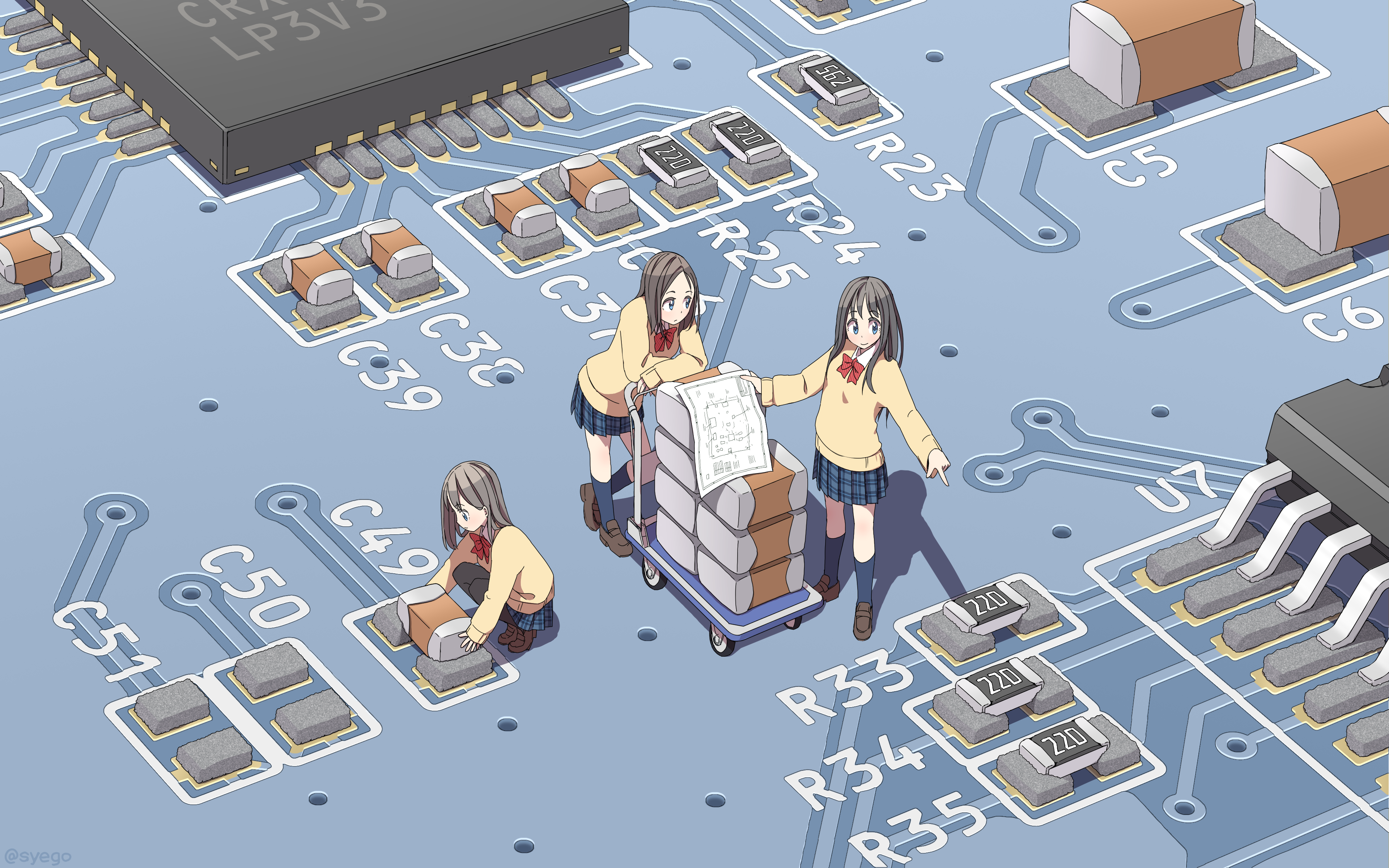
我们先来看第一个组合逻辑电路的波形图:
让我们来分析一下:
- 输入:
a和b - 输出:
q
观察波形:
- 当
a和b都为1时,q为1 - 其他情况,
q都为0
所以逻辑关系很简单:q = a & b(与运算)
生活实例类比:这就像一扇需要两把钥匙同时打开的门,只有当a和b都有钥匙(为1)时,门才会打开(q为1)。
代码实现
1 | module top_module ( |
要点小结
- 对于组合逻辑电路,先列出真值表,然后写出逻辑表达式
- 简单的逻辑关系可以直接观察波形得出
- 组合逻辑使用
assign连续赋值语句
Combinational circuit 2
波形分析
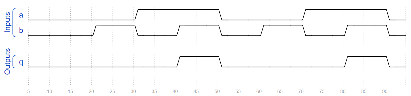
第二个组合逻辑电路稍微复杂一点:
输入有4个:a、b、c、d
输出有1个:q
这种情况下,我们可以列出真值表,然后写出最小项之和的形式(SOP)。
观察波形,找出所有q=1的情况:
a=0, b=0, c=0, d=0→ 1a=0, b=0, c=1, d=1→ 1a=0, b=1, c=0, d=1→ 1a=0, b=1, c=1, d=0→ 1a=1, b=0, c=0, d=1→ 1a=1, b=0, c=1, d=0→ 1a=1, b=1, c=0, d=0→ 1a=1, b=1, c=1, d=1→ 1
代码实现
1 | module top_module ( |
要点小结
- 对于多输入的组合逻辑,可以列出真值表,然后写出最小项之和
- 这种方法虽然繁琐,但最直接,不容易出错
- 注意操作符的优先级:
&比|高,所以不需要括号
Combinational circuit 3
波形分析
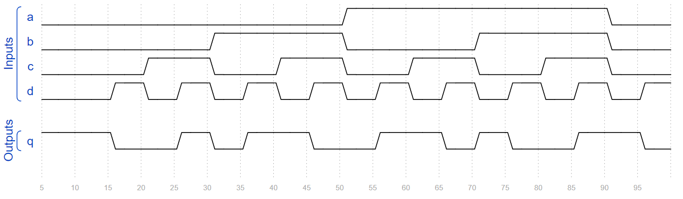
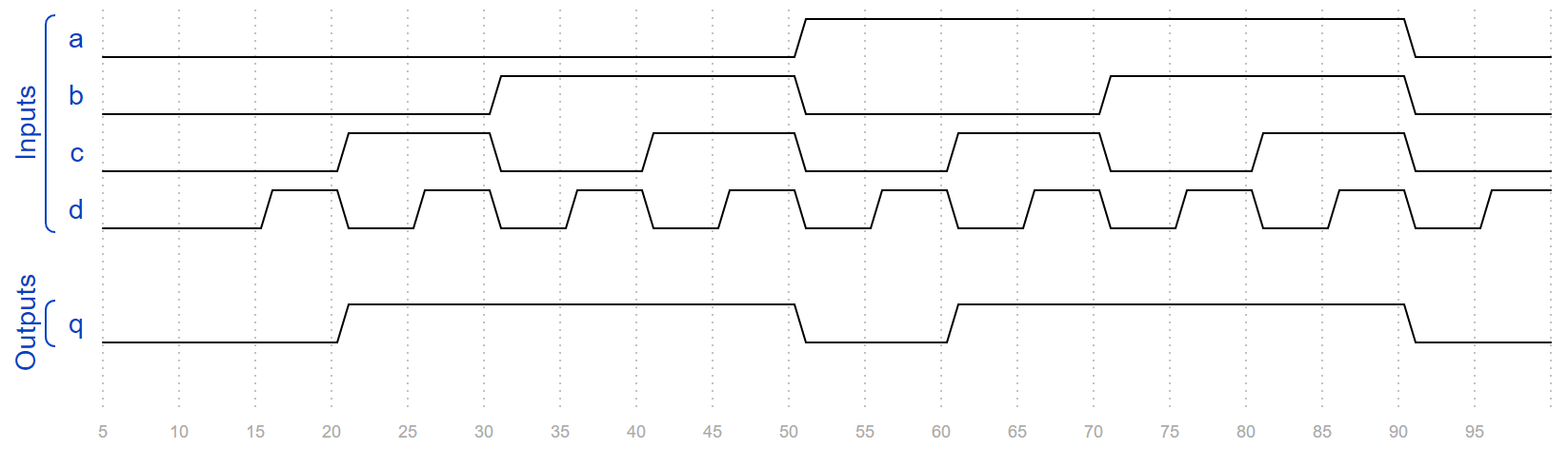
第三个组合逻辑电路:
还是4个输入,1个输出。如果我们直接写最小项之和,会很繁琐。这时候可以用卡诺图(Karnaugh Map)来化简。
通过卡诺图化简,我们可以得到更简洁的表达式:
q = b & d | b & c | a & d | a & c
生活实例类比:这就像一个多重条件的门禁系统,只要满足以下任一条件就可以进入:
- 有b和d权限
- 有b和c权限
- 有a和d权限
- 有a和c权限
代码实现
1 | module top_module ( |
要点小结
- 卡诺图是化简逻辑表达式的有力工具
- 化简后的电路使用更少的门,面积更小,速度更快
- 简单的电路可以直接写化简后的表达式,复杂的电路建议用工具自动综合
Combinational circuit 4
波形分析
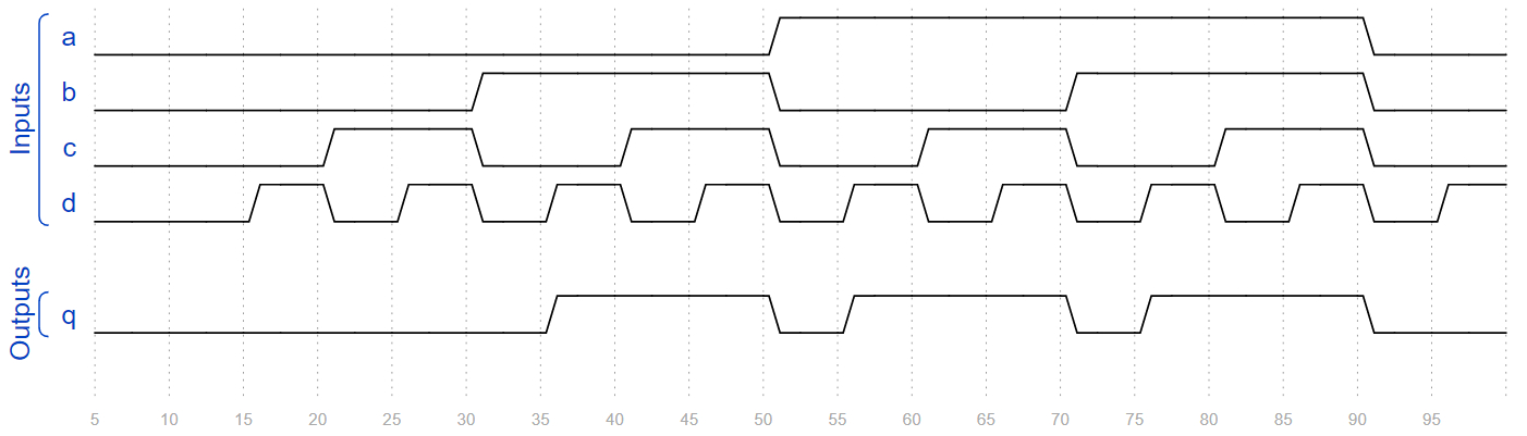
第四个组合逻辑电路:
观察波形可以发现,这个电路的逻辑非常简单:
- 只要
b或c有一个为1,q就为1 - 只有当
b和c都为0时,q才为0
所以逻辑表达式是:q = b | c(或运算)
代码实现
1 | module top_module ( |
要点小结
- 不是所有的输入都会在电路中用到,要仔细观察波形
- 未使用的输入在代码中保留即可,不用处理
- 如果综合工具报警告说某个输入未使用,可以忽略,只要功能正确就行
Combinational circuit 5
波形分析
第五个组合逻辑电路很有趣:
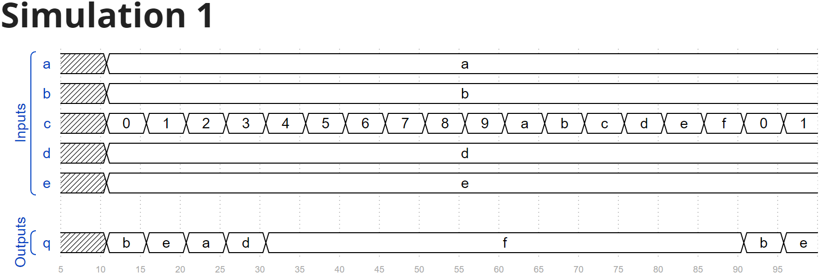
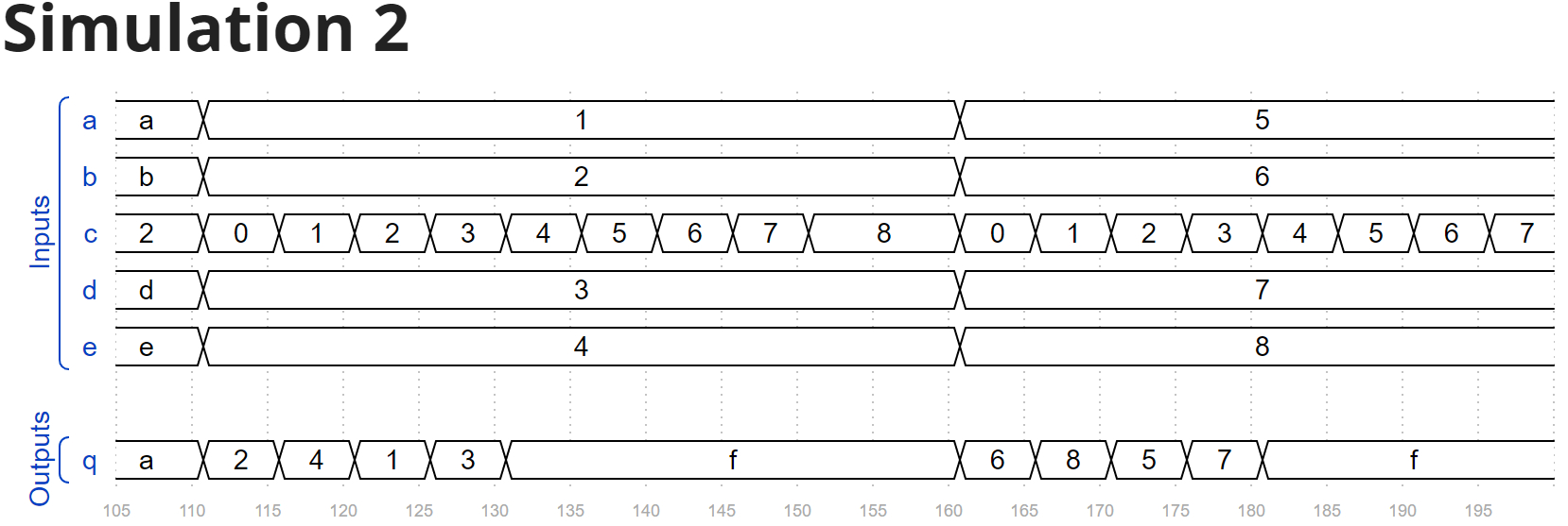
从波形图可以看出,这是一个多路选择器(MUX):
- 输入:5个4位数据
a、b、c、d、e - 选择信号:
c(注意这里名字有点混淆,选择信号也叫c) - 输出:
q
通过观察波形,我们可以得到选择关系:
c=0时,选择bc=1时,选择ec=2时,选择ac=3时,选择d- 其他情况,输出
0xf
代码实现
1 | module top_module ( |
要点小结
- 多路选择器使用
case语句实现最清晰 - 注意这道题中输入信号
c同时也是选择信号,名字有点混淆 - 一定要加上
default分支,否则会产生锁存器
Combinational circuit 6
波形分析
第六个组合逻辑电路是一个查表电路:
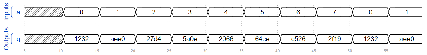
功能很简单:
- 输入:3位信号
a - 输出:16位信号
q - 根据
a的值,输出对应的16位数据
这就像一个只读存储器(ROM),a是地址,q是对应地址的数据。
代码实现
1 | module top_module ( |
要点小结
- 查表电路是组合逻辑的常见应用
- 使用
case语句实现查表最直观 - 这种电路在实际中常用于:
- 波形生成
- 字符显示
- 数学函数查表(如正弦表)
Sequential circuit 7
波形分析
现在我们来看时序逻辑电路!第一个时序电路:
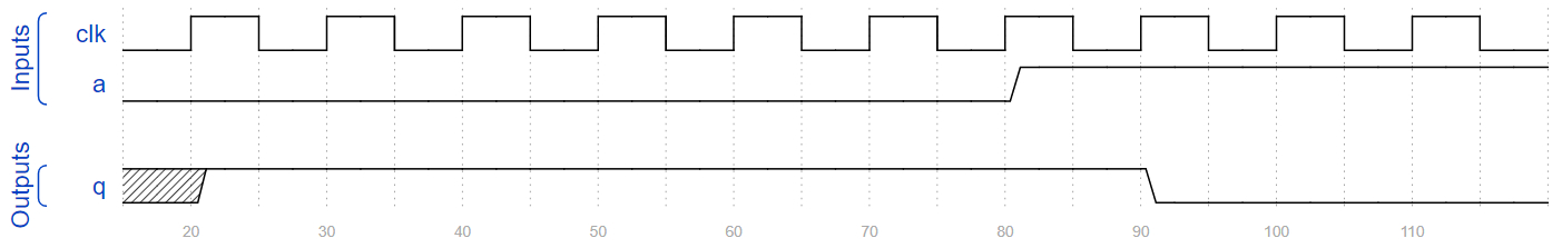
时序逻辑和组合逻辑最大的区别是:时序逻辑有时钟信号,输出不仅取决于当前输入,还取决于历史状态。
让我们分析这个电路:
- 时钟:
clk(上升沿触发) - 输入:
a - 输出:
q
观察波形:
- 在每个时钟上升沿,
q会更新为~a(a的反) - 这是一个D触发器,D端输入是
~a
代码实现
1 | module top_module ( |
要点小结
- 时序逻辑使用
always @(posedge clk)来描述 - 时序逻辑中使用非阻塞赋值
<= - 输出在时钟上升沿更新,其他时间保持不变
Sequential circuit 8
波形分析
第二个时序电路稍微复杂一点:
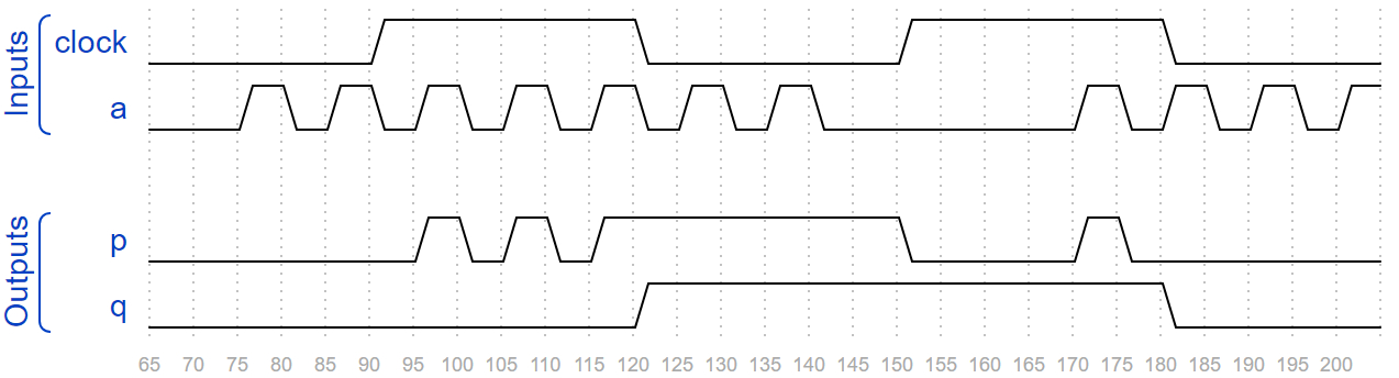
这个电路有两个输出:p和q。
让我们分别分析:
输出p:
- 这是一个锁存器:当
clock为高电平时,p = a;当clock为低电平时,p保持原值 - 注意:题目中时钟信号叫
clock,不是clk
输出q:
- 这是一个D触发器,在
clock的下降沿触发 - 它的输入是
p,所以在时钟下降沿,q会更新为当前的p值
生活实例类比:
p就像一个透明的门锁:当clock高电平时,门是透明的,a可以直接传到p;当clock低电平时,门锁上,p保持不变q就像一个照相机:在时钟下降沿时,给p拍一张照,然后保存下来
代码实现
1 | module top_module ( |
要点小结
- 锁存器是电平敏感的,触发器是边沿敏感的
posedge是上升沿,negedge是下降沿- 锁存器在现代设计中通常不推荐使用,因为容易产生时序问题
Sequential circuit 9
波形分析
第三个时序电路是一个计数器:
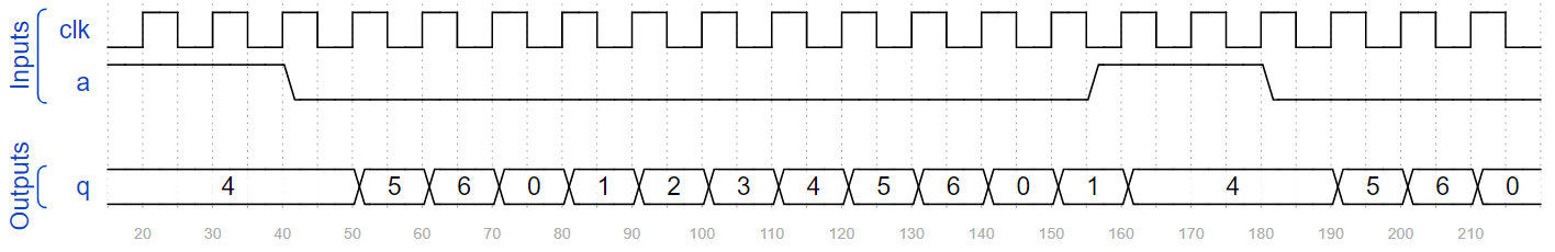
让我们分析一下这个计数器的行为:
- 正常情况下(
a=0),计数器从0到6循环计数:0→1→2→3→4→5→6→0→… - 当
a=1时,计数器保持在4不变 - 当
a变回0后,计数器继续从4开始往下计数
生活实例类比:这就像一个电梯,正常情况下从1楼到7楼循环运行。但当有人在4楼按下停止按钮(a=1),电梯就会一直停在4楼。直到松开按钮(a=0),电梯才继续运行。
代码实现
1 | module top_module ( |
要点小结
- 计数器的设计要注意:
- 计数范围(这道题是0-6)
- 计数条件(什么时候加1,什么时候保持)
- 复位条件(如果有的话)
- 条件判断的顺序很重要:先检查保持条件,再检查计数边界
Sequential circuit 10
波形分析
最后一个时序电路稍微复杂一点:
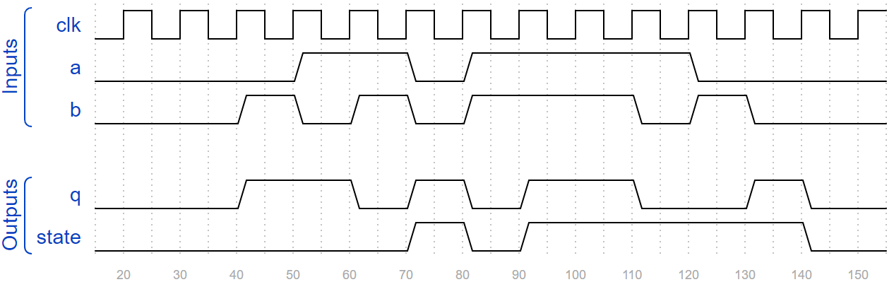
这个电路有两个输入(a、b),两个输出(q、state)。
让我们先分析输出q:
- 观察波形可以发现,
q是a、b和state的异或:q = a ^ b ^ state
再分析状态state:
state是一个D触发器,在时钟上升沿更新- 观察
state的变化规律:- 当
a=1且b=1时,下一状态state=1 - 当
a=0且b=0时,下一状态state=0 - 其他情况,
state保持不变
- 当
代码实现
1 | module top_module ( |
要点小结
- 对于复杂的时序电路,可以分开分析:
- 先分析组合逻辑部分(输出
q) - 再分析时序逻辑部分(状态
state)
- 先分析组合逻辑部分(输出
- 列出真值表有助于分析逻辑关系
- 保持状态的语句
state <= state可以省略,写上只是为了更清晰
入门者避坑指南
从波形图反推电路时,初学者很容易犯一些错误。下面我总结了最常见的5个问题:
坑点1:混淆组合逻辑和时序逻辑
错误表现:1
2
3// 错误示例:应该用时序逻辑,却用了组合逻辑
// 题目要求是D触发器,但写成了组合逻辑
assign q = ~a; // 应该在always @(posedge clk)中
错误原因:
- 没有仔细看波形图中是否有时钟信号
- 没有注意输出是否是在时钟边沿更新的
正确做法:1
2
3
4// 正确示例:时序逻辑
always @(posedge clk) begin
q <= ~a;
end
调试技巧:
- 先看波形图中有没有时钟信号
- 看输出是立即变化(组合逻辑),还是在时钟边沿变化(时序逻辑)
坑点2:阻塞赋值和非阻塞赋值使用错误
错误表现:1
2
3
4// 错误示例:在时序逻辑中使用阻塞赋值
always @(posedge clk) begin
q = ~a; // 应该用<=,不是=
end
错误原因:
- 没有记住:时序逻辑用非阻塞赋值
<=,组合逻辑用阻塞赋值=
正确做法:1
2
3
4
5
6
7
8
9
10// 正确示例
// 组合逻辑
always @(*) begin
q1 = a & b;
end
// 时序逻辑
always @(posedge clk) begin
q2 <= a & b;
end
调试技巧:
- 记住这个简单的规则:
- 组合逻辑(
always @(*)):用= - 时序逻辑(
always @(posedge clk)):用<=
- 组合逻辑(
坑点3:漏掉时钟边沿类型
错误表现:1
2
3
4// 错误示例:应该是下降沿触发,写成了上升沿
always @(posedge clock) begin // 应该是negedge
q <= p;
end
错误原因:
- 没有仔细观察波形图中输出是在哪个边沿变化的
正确做法:1
2
3
4// 正确示例:下降沿触发
always @(negedge clock) begin
q <= p;
end
调试技巧:
- 在波形图中画一条垂直线,看输出是在上升沿变化还是下降沿变化
- 注意时钟信号的名字可能是
clk、clock等
坑点4:信号位宽错误
错误表现:1
2
3
4// 错误示例:位宽不匹配
input [3:0] a;
output q; // 应该是[3:0]
assign q = a;
错误原因:
- 没有仔细看波形图中信号是几位的
正确做法:1
2
3
4// 正确示例
input [3:0] a;
output [3:0] q;
assign q = a;
调试技巧:
- 看波形图中信号是几位的(比如有没有显示十六进制,或者多位一起变化)
- 检查输入输出的位宽是否匹配
坑点5:状态机设计错误
错误表现:1
2
3
4
5
6// 错误示例:没有考虑所有情况
always @(posedge clk) begin
if (a & b)
state <= 1;
// 漏掉了其他情况!
end
错误原因:
- 没有完整分析波形图中状态的变化规律
- 没有列出所有可能的输入组合
正确做法:1
2
3
4
5
6
7
8
9
10
11
12// 正确示例
always @(posedge clk) begin
if (a & b) begin
state <= 1'b1;
end
else if (~a & ~b) begin
state <= 1'b0;
end
else begin
state <= state; // 保持不变
end
end
调试技巧:
- 先画出完整的状态转移图或真值表
- 确保所有可能的输入组合都有对应的处理
- 如果有保持状态的情况,要明确写出来(或者给默认值)
结语
这一章的内容非常有趣,也非常实用。从波形图反推电路,是数字电路设计工程师的一项基本功。
笔者认为,要掌握这项技能,关键在于多练习:
- 先从简单的组合逻辑开始,熟悉基本的逻辑门
- 然后学习时序逻辑,理解触发器和锁存器的区别
- 最后挑战复杂的状态机和计数器
另外,建议大家在学习时,自己也多画波形图,这样可以更好地理解电路的行为。
下一章是HDLBits的最后一章:编写Testbench。这也是非常重要的一章,因为只有通过仿真验证,我们才能确保电路的功能是正确的。敬请期待!
 微信
微信 支付宝
支付宝